KA2211, 5.8W Stereo Audio Amplifier

Tags
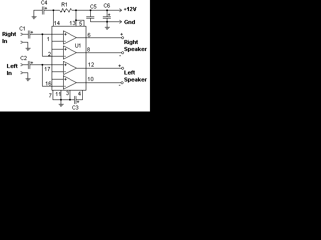
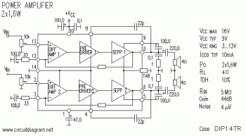
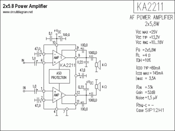
The following schematic is the diagram of 5.8 stereo power amplifier based on Samsung IC KA2211. The 5.8W is the power output on each channel, it means that the output will be 2 x 5.8W (maximum).

KA2211, 5.8W Stereo Audio Amplifier


About KA2211:
KA2211 is a dual audio power amplifier for consumer application. It is designed for high power, low dissipation dan low noise. Is also contains various of protectors and suitable for high performance car audio power amplifier.

Download the datasheet document of KA2211 HERE

TDA1521 / TDA1521Q: 12W Stereo Amplifier

Tags
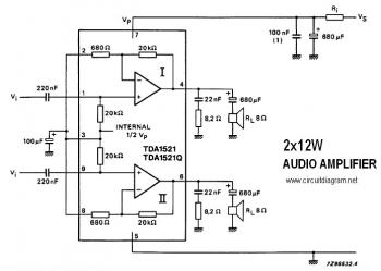
This is a stereo audio amplifier circuit that provides 12W output power on each audio channel. This simple circuit is built on a single integrated circuit of TDA1521 / TDA1521Q, and only supported by few external components.

TDA1521 / TDA1521Q: 12W Stereo Amplifier


TDA1521/TDA1521Q is a dual high-fidelity audio amplifier encapsulated in a plastic 9-leads. The device is specially designed for power supply applications (eg, stereo TV and radio). A heatsink is needed to prevent overheating the IC.

TDA1521/TDA1521Q features:
  • Requires very few external components
  • Low offset voltage between output and ground
  • Input muted during power-on and off
  • (no switch-on or switch-off clicks)
  • Hi-fi according to IEC 268 and DIN 45500
  • Excellent gain balance between channels
  • Short-circuit-proof
  • Thermally protected
This hi-fi stereo power amplifier is designed for mains fed applications. The circuit is designed for both symmetrical and asymmetrical power supply systems. An output power of 2 x 12 watts (THD = 0,5%) can be delivered into an 8 W load with a symmetrical power supply of ± 16 V.

Download the TDA1521/TDA1521Q Datasheet Here

Basic Monostable Multivibrator based IC 555

Tags
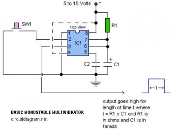
The following diagram is the circuit diagram of the very basic monostable multivibrator which built based on timer IC 555.

Basic Monostable Multivibrator based IC  555 circuit


Parts list:
R1 = see notes
C1 = see notes
C2 = 10nF
IC1 = LM555

Notes:
  • R1 and C1 determine length of output pulse where t=R1xC1 and R1 is in ohms and C1 is in farads.
  • Pin 4 is the RESET. Leave it connected to power supply (+V) during normal operation. Bring pin 4 AND pin 2 low at the same time to reset timing cycle.

Portable Amplifier based on TEA2025

Tags

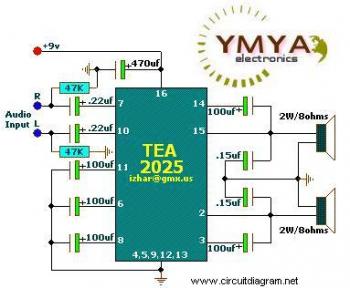
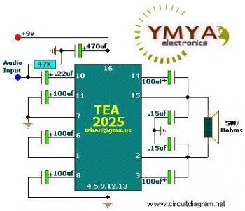
This is the diagram of simple portable amplifier circuit. This amplifier circuit build based on IC TEA2025 that is a monolithic integrated audio amplifier of 16-pin plastic dual in line package built by UTC manufacture. The circuit has an internal thermal protection. The circuit designed for portable cassette players and radios. You can also use as PC audio amplifier.

Here the amplifier diagram for stereo audio input/output:

Portable Amplifier based on TEA2025

and here the amplifier with mono audio input/output (bridge):

Portable Amplifier based TEA2025

Stereo per channel
VCC=9V; RL=4 ohm/3W
VCC=9V; RL=8 ohm/2W

Bridge Application
VCC=9V; RL=8 ohm/5W
VCC=9V; RL=4 ohm/8W

Supply Voltage min = DC3v @ 500mA
Supply Voltage max = DC12v @ 500mA
Supply Voltage recommended = DC9v @500mA

Download TEA2025 Datasheet
Download the schematic diagram in PDF format HERE

2x22W Stereo Power Amplifier circuit based TDA1554

Tags
This is is a stereo power amplifier circuit works up to 22W on each channel. It will be 2x22W output. A few externel components required to support the main component of TDA1554. Heatsink on the power IC is a must to prevent overheating on the power IC. The chip should run cool enough to touch with the proper heatsink installed.

22W Power Amplifier with TDA1554 circuit

Component part list:

R1__________39K 1/4 Watt Resistor
C1,C2_______10uf 25V Electrolytic Capacitor
C3__________100uf 25V Electrolytic Capacitor
C4__________47uf 25V Electrolytic Capacitor
C5__________0.1uf 25V Ceramic Capacitor
C6__________2200uf 25V Electrolytic Capacitor
U1__________TDA1554 Two Channel Audio Amp Chip
MISC________Heatsink For U1, Binding Posts (For Output), RCA Jacks (For Input)

Operated at 12 Volts and at about 5 Amps at full volume. Lower volumes use less current, and therefore produce less heat. Printed circuit board is preferred, but universal solder or perf board will do. Keep lead length short.

LM3886 , 100W Power Audio Amplifier circuit

Tags
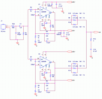
The following circuit diagram is the 100 Watt power audio amplifier circuit, build based on power amp chip LM3886. The single chip of IC LM3886 is able to amplify the audio power output up to 68W.

LM3886 , 100W Power Audio Amplifier  circuit diagram

In this circuit, the two of LM3886 are paralled to gain more powerful amplifier output. This amplifier can deliver about 50W into a 8-ohm speaker and 100W into a 4-ohm speaker. To make a stereo amplifier, there are should be use 4 pieces of LM3886.

Circuit source: http://www.shine7.com/audio/pa100.htm

20W Bridge Car Amplifier based TDA7240A

Tags

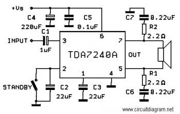
The following circuit diagram is a bridge amplifier which specially designed for car audio system. The circuit is very simple with few external components supporting the power IC TDA7240A. This circuit will produce a maximum power output of 20W

Schematic Diagram:

20W Bridge Amplifier circuit diagram

PCB Layout:

20W Bridge Car Amplifier pcb layout based TDA7240A


The circuit diagram and PCB layout come from the IC TDA7240A datasheet. Download TDA7240A datasheet for circuit reference.

Positive Variable Power Supply circuit

The following diagram is the schematic diagram of positive adjustable/variable power supply. It means that the power supply output will be DC current with positive [+] and ground [0] polarity.

Schematic diagram:
Positive Variable Power Supply circuit


Power Supply Input:


Component part list:
R1 = 330
R2 = 1K
VR1 = 10K 10-turn trimpot
C1 = 2200uF/50V
C2,4 = 100nF ceramic
C3,4 = 10uF/63V
D1-6 = 1N5403
REG IC = LM317T
Heatsink

Visit this page to download the variable power supply diagram manual.

32W HiFi Amplifier circuit based on TDA2050

Tags

This is a High Fidelify (Hi-Fi) amplifier circuit based on single IC TDA205. This is a mono channel audio amplifier. You need to build the same circuit for stereo channel.

Schematic diagram:
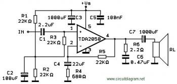
32W HiFi Amplifier circuit based on TDA2050


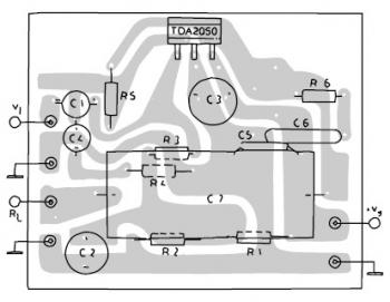
PCB Design:

TDA2050 Amplifier PCB layout

TDA2050 Description:
The TDA 2050 is a monolithic integrated circuit in Pentawatt package, intended for use as an audio class AB audio amplifier. Thanks to its high power capability the TDA2050 is able to provide up to 35W true rms power into 4 ohm load @ THD =10%, VS = ±18V, f = 1KHz and up to 32W into 8ohm load @ THD = 10%, VS = ±22V, f = 1KHz. Moreover, the TDA 2050 delivers typically 50W music power into 4 ohm load over 1 sec at VS=22.5V, f = 1KHz.

The high power and very low harmonic and crossover distortion (THD = 0.05% typ, @ VS = ±22V, PO = 0.1 to 15W, RL=8ohm, f = 100Hz to 15KHz) make the device most suitable for both HiFi and high class TV sets.

Download TDA2050 datasheet for the circuit reference.
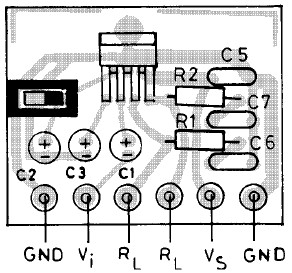
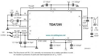
TDA7295, 80W Audio Amplifier

Tags
Below is a schematic diagram of the 80W power amplifier based on single Power IC TDA7295. With simple diagram, this circuit will be easy to build.

TDA7295, 80W Audio Amplifier circuit diagram


The IC TDA7295 is a monolithic integrated circuit , intended for use as audio class AB amplifier in Hi-Fi field applications such as home theatre and topclass TV.

Continue reading about this 80W audio amplifier.

Triangle Wave and Square Wave Generator

Tags
This is a simple circuit diagram of triangle wave and square wave generator.


The circuit is designed based on a common 1458 dual op-amp that can be used from very low frequencies to about 10 Khz. The time interval for one half cycle is about R*C and the outputs will supply about 10 milliamps of current. Triangle amplitude can be altered by adjusting the 47K resistor, and waveform offset can be removed by adding a capacitor in series with the output.

source of Triangle Wave and Square Wave Generator circuit:
http://www.high-voltage-lab.com/211/triangle-squarewave-generator

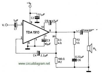
10W Audio Amplifier circuit based on TDA1910

Tags

Simple and cheap, that's the advantage of this circuit. Although the output power is not high but audio quality is good, because TDA1910 has a very low noise feature. This circuit suitable for use as a student project.

10W Audio Amplifier circuit based on TDA1910


About TDA1910:
The TDA1910 is a monolithic integrated circuit in MULTIWATT® package, intended for use in Hi-Fi audio power applications, as high quality TV sets.

The TDA 1910 meets the DIN 45500 (d = 0.5%) guaranteed output power of 10W when used at 24V/4W. At 24V/8W the output power is 7W min.

TDA1910 Features:

  • muting facility
  • protection against chip over temperature
  • very low noise
  • high supply voltage rejection
  • low “switch-on” noise.

Download TDA1910 Datasheet for complete TDA1910 reference

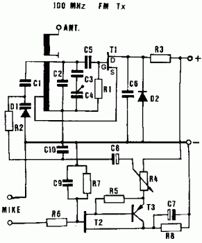
Simple FM Transmitter

Tags
This FM transmitter claimed to be a very good transmitter. This circuit is worked very well since this circuit is actually copied from available electronic kit.
Simple FM Transmitter circuit diagram

Component part:

R1 100K
R2 220K
R3 22R
R4 1K trimmer
R5 1K
R6 56K
R7 1M
R8 1K2
T1 BF244A or BF245A FET
T2 2N3819 FET
T3 BC307/8/9 or BC557/8/9 PNP

D1 Varicap diode (eg. BB119)
D2 1N4148
C1 5pF ceramic
C2 6pF ceramic
C3 15pF ceramic
C4 trimmer cap
C5 15pF ceramic
C6 1nF ceramic
C7 100uF electrolytic
C8 4.7uF electrolytic
C9 100pF ceramic


Frequency range is 100-108 MHz. The circuit is only mono circuit, and accepts an audio input from either a microphone or other source. The input impedance is 1Mohm. The input sensitivity is 5mV and the max input signal is 10mV. The transmitted signal can be picked up on a FM radio. The circuit can be used for short-range transmission, eg. for wireless microphones.

The power supply to use is 9-14 V DC, one of the little rectangular 9V batteries is fine. Connect this to the + and - points on the PCB. The sound input goes to the points marked "MIKE". The antenna should be connected to the point marked "ANT". The emitter's output impedance is 50 ohms. You can make your own fancy antenna if you like.

Source: http://www.high-voltage-lab.com/77/small-radio-transmitter

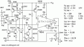
50W Power Amplifier circuit based on STK-1050

Tags
Here is one of the circuit diagram of a power amplifier with the STK1050 single power chip which is supported by several components that make a better sound output. This amplifier is a single output amplifier, so if you want a stereo amplifier, then you must make a similar circuit.

50W Power Amplifier with STK-1050 circuit diagram

STK-1050 Features:
STK1050 has some features that make it superior and good for your audio amplifier.

  1. Does not require externally connected emitter resistors.
  2. Values of emitter resistors have carefully been reviewed to provide superior characteristics.
  • Better supply voltage utilization permits designing power supply voltage that are about 0.7V (for RL=4ohms) lower than those required for previous DPP models.
  • Maximum allowable power consumption for each resistor is 5W or higher, permitting accomodation for all loads.
  • Peak allowable current is 18A or more, providing an ample margin even for peak currents under when short circuited or similar emergencies.
  • In particular, maximum output 4 ohms have been enormously improved.

  1. Use of emitter resistors facilitates meeting different safety standards and designing PCBs
  2. Mutual interferences in the high-frequency range caused by layout of externally connected emitter resistors no longer exist. This facilitates lower distortion factors.
  3. Pins are used for emitter resistor output terminals that were not conected in previous DPPs. All other terminals remain uncharged; there is no need for major circuit board changes.

Download STK-1050 datasheet

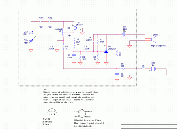
One Transistor FM Radio

Tags
Thi circuit is very simple with only one transistor. No need additional active components, but if you want to hear the sound louder, just build another amplifier circuit... :)

One Transistor FM Receiver circuit diagram

Part designator Part description
C1a,C1b 10 pf, 50 v, ceramic disc capacitor
C2 22 pf, 50 v, ceramic disc capacitor
C3 RF tuning capacitor
C4 330 pf, 50 v, ceramic disc capacitor
C5,C8 0.001 uf, 50 v, ceramic disc capacitor
C6 0.22 uf, 50 v, film capacitor
C7 0.0047 uf, 50 v, ceramic disc capacitor
C9 22 uf, 16 v, electrolytic capacitor
D1 TL431AIZ voltage control Zener (shunt regulator)
EPH1 High impedance earphone
L2 22 uh RF choke
Q1 2N4416A JFET transistor
R1 470K, 1/4 w, resistor
R2, R3 1K, 1/4 w, resistor
R4 10K, 1/4 w, resistor
R5 1M, 1/4 w, resistor
R6 100 ohm, 1/4 w, resistor
S1 Small SPST switch
screws for C3 screws for mounting C3 (2 needed)
nylon screw #4 nylon screw used for tuning C3
battery connector mini battery snap


More instruction how to build this circuit, visit this page

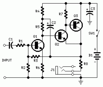
Portable headphone amplifier circuit

Tags
This is an easy built portable headphone amplifier circuit. You can use this headphone amplifier to amplify your radio receiver, mp3/mp4 player, computer or dvd/cd player. You may connected the input channel directly to those devices.
Portable headphone amplifier circuit

R1 _______________ 10K
R2 _______________ 100K
R3 _______________ 68K (see notes)
R4 _______________ 1K5
R5 _______________ 3K3
R6 _______________ 330R
R7 _______________ 4K7
R8 _______________ 2R2
C1 _______________ 1uF 63V
C2 _______________ 100uF 25V
C3 _______________ 470uF 25V
Q1 _______________ BC239C 25V 100mA NPN High-gain Low-noise Transistor
Q2 _______________ BC337 45V 800mA NPN Transistor
Q3 _______________ BC327 45V 800mA PNP Transistor
J1 _______________ Stereo 3mm. Jack socket
SW1 _______________ SPST Switch
B1 _______________ 3V Battery (2xAAA)


R3 value was calculated for headphone impedance up to 300 Ohms. Using 600 Ohms loads or higher, change R3 value to 100K.
Take a note that above circuit only show single channel.

1.2Watt Mini Audio Amplifier Circuit based KA2214

Tags

This mini audio amplifier circuit is based on power IC KA series. This mini amplifier delivers dual audio output (stereo) at 1.2W on each channel.

1.2Watt Mini Audio Amplifier Circuit based KA2214

The KA2214 is a monolithic integrated dual audio power amplifier in a 14-pin plastic dual in line package. It is designed portable audio sets.

Download the KA2214 datasheet for detail features and specifications.

TDA2040 - 20W HI-FI Audio Amplifier

Tags

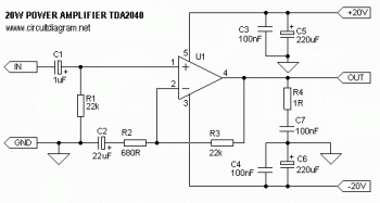
Here the hi-fi power amplifier circuit which will deliver 20W power output. This amplifier circuit use single power IC TDA2040 and a few external components.

TDA2040 - 20W HI-FI Audio Amplifier  circuit diagram


Detailed explanation about this 20W Power Amplifier

Simple FM Radio Receiver Circuit with TDA7021T

Tags

Here the simple FM radio receiver circuit built based single IC TDA7021T.

Simple FM Radio Receiver  with TDA7021T circuit diagram

Component Parts List:

R1 = 8kΩ2
R2 = 10kΩ
R3 = 390Ω
C1,C3 = 10nF
C2,C6,C9,C16 = 100nF
C4 = 33pF
C5 = 25pF trimmer (Murata type TZB4Z250AB10R00)
C7,C10 = 1nF5
C8 = 820pF
C11 = 1nF
C12 = 68pF
C13 = 220pF
C14 = 47μF 10V (Nichicon UWX1A470MCL1GB 5.5mmL chip type)
C15 = 3nF3
L1 = 36nH (4 turns 0.5mm silver-plated wire, inside diameter 4mm; length 7mm)
L2 = 1μH, SMD case 0805 (fres > 300 MHz)
IC1 = TDA7021T (SMD in SO16 case)


Complete explanation, visit this site

AM Receiver circuit with MK484

Tags

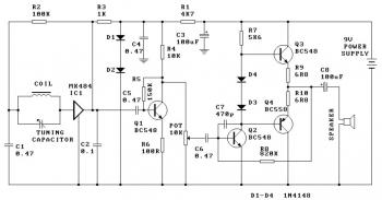
This is a AM Receiver with single IC MK484. If your are interested to build this radio circuit, you may buy the kits include the component part list at kitsrus.com.

One Chip AM Radio Receiver circuit diagram

Part list:

R9, R10_________ 6R8
R6_____________ 100R
R3_____________ 1K
R1_____________ 4K7
R7_____________ 5K6
R4_____________ 10K
R2_____________ 100K
R5_____________ 150K
R8_____________ 820K
Pot_____________ 10K log pot
Coil & ferrite bar set
C7______________ 470p ceramic
C, C4, C5, C6_____ 470nF monoblock
C2______________ 100nF monoblock
C3, C8___________ 100uF electrolytic capacitor
VariCap__________ 60/160 AM tuning cap
D1, D2, D3, D4____ 1N4148 diode
Q1, Q3___________ BC548
Q2______________ BC558
IC1_____________ MK484 AM radio IC TO92
Speaker__________ 0.5 or 1W, 8 ohm speaker

Visit this AM Radio Receiver for more explanation.

Really Simple LED Flasher with LM3909

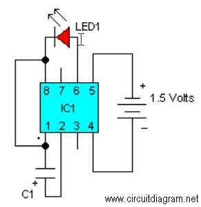
This is a very -very easy and simple LED flasher circuit with only needs three components that are: a flasher IC, a LED and a electrolytic capacitor.

LED Flasher with LM3909

Component list:

LED1_________Red LED
C1___________100uf/16V
IC1__________LM3909

Very nice for electronics newbie.. :)

Really Simple Audio Pre-Amplifier

Tags
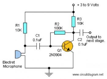
This pre-amp circuit is very simple. It's just need 1 active component (transistor) to gain the input. You may build similar circuit for your stereo sound system.

schematic diagram:

Really Simple Audio Pre-Amplifier schematic

This easy circuit provides good gain to weak audio signals such as electret microphone. Use it in front of an RF oscillator to make an RF transmitter that’s very sensitive to sound.