High-End Audio Modular Preamplifier

Tags
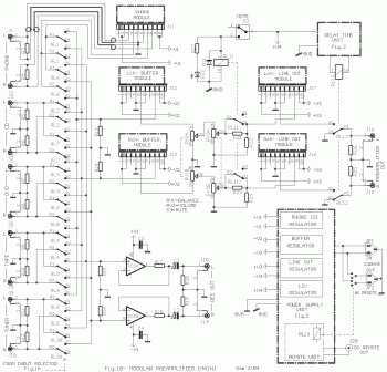
This circuit isn't easy to built but you will get a great audio quality from this circuit. This circuit will give u a high quality preamplifier, capable to drive high quality power amplifiers with good sound.
High-End

See the explanation here.

Digital Clock

Digital Clock circuit diagram

Digital Clock circuit diagram

This is digital clock schematic diagram. This circuit is quite complex and quite difficult for a newbie because this circuit uses IC with some a complicated connections. The voltages that supplied to the circuit are divided in two lines.

Small Surround Sound Decoder

Tags
Small Surround Sound Decoder  circuit diagram

This is surround sound decoder. With this circuit, you can divide the 2 channel (R and L channel) stereo output become 4 channel output that are R channel, L channel, Center out and Rear out. This circuit will enrich your audio sound system.

For full explanation about this circuit, please visit this PAGE

3-3.5 Watt FM transmitter circuit

Tags
This is 3-3.5 Watt FM transmitter circuit. With this power, it should be able to reach 3-5 KM distance. The frequency range is about 90-110 MHz.

FM transmitter circuit circuit diagram

Component list
PartTotal Qty.Description
R1,R4,R14,R15410K 1/4W Resistor
R2,R3222K 1/4W Resistor
R5,R1323.9K 1/4W Resistor
R6,R112680 Ohm 1/4W Resistor
R71150 Ohm 1/4W Resistor
R8,R122100 Ohm 1/4W Resistor
R9168 Ohm 1/4W Resistor
R1016.8K 1/4W Resistor
C114.7pF Ceramic Disc Capacitor
C2,C3,C4,C5,C7,C11,C127100nF Ceramic Disc Capacitor
C6,C9,C10310nF Ceramic Disc Capacitor
C8,C14260pF Trimmer Capacitor
C13182pF Ceramic Disc Capacitor
C15127pF Ceramic Disc Capacitor
C16122pF Ceramic Disc Capacitor
C17110uF 25V Electrolytic Capacitor
C18133pF Ceramic Disc Capacitor
C19118pF Ceramic Disc Capacitor
C20112pF Ceramic Disc Capacitor
C21,C22,C23,C24440pF Trimmer Capacitor
C2515pF Ceramic Disc Capacitor
L115 WDG, Dia 6 mm, 1 mm CuAg, Space 1 mm
L2,L3,L5,L7,L956-hole Ferroxcube Wide band HF Choke (5 WDG)
L4,L6,L831.5 WDG, Dia 6 mm, 1 mm CuAg, Space 1 mm
L1018 WDG, Dia 5 mm, 1 mm CuAg, Space 1 mm
D11BB405, BB102 or equal (most varicaps with C = 2-20 pF [approx.])
Q112N3866
Q2,Q422N2219A
Q31BF115
Q512N3553
U117810 Regulator
MIC1Electret Microphone
MISC1PC Board, Wire For Antenna, Heatsinks


Source: electronic-lab.com

Mini FM Transmitter

Tags
Here the schematic diagram of mini and simple fm transmitter.

Supply voltage : 1.1 - 3 Volts
Power consumption : 1.8 mA at 1.5 Volts
Range : 30 meters max. at 1.5 Volts

Mini FM Transmitter circuit diagram

Here the PCB Layout:

Mini FM Transmitter circuit diagram

Visit this page for complete explanation

3 Line Mixer

Tags
Actually, you can modify this circuit become more than 3 lines mixer. Just add and repeat the input parts (P=10K R=22K).

Schematic diagram:
3 Line Mixer circuit diagram

Component placement:
3 Line Mixer circuit diagram

PCB layout:
3 Line Mixer circuit diagram

500 Watt Power Inverter

Here the 500 Watt power inverter schematic diagram.

Designed by: Syed Ashad Mustafa Younus
Revised by: Ronnie B. Tabanao

500 Watt Power Inverter circuit diagram


Click the image to get bigger size of schematic diagram and then save the image... or download the circuit diagram from here